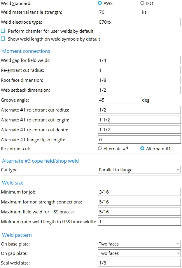
Weld Design Settings
- General Overview
- Tips and Tricks
- Related Tools
'
AWS ' stands for American Welding Society.
'
Weld material tensile strength (ksi or MPa) : The tensile strength of the weld material. Connection design checks this value to ensure that appropriate welding equipment is being used for shop welding of welded connections.
For example, if you are using an AISC " Connection design method ," then connection design generates the end connection failure message "Minimum weld metal ten. strength is 70 ksi ; 483 MPa" for shear tab connections whose "Weld material tensile strength" is less than 70 ksi (483 MPa).
Units: Be sure to make your entry is in kips/sq. inch (ksi) if you are using ' Imperial ... ' dimensioning, in MPa if you are using ' Metric ' dimensioning.
Weld electrode type: The electrode type entered here appears on the Connection Design Calculations and Expanded Connection Design Calculations reports but does not directly affect the connection design .
Perform chamfer for user welds by default: ![]() or
or ![]() . This applies to welds that are added using Add Weld or Add Weld Layout .
. This applies to welds that are added using Add Weld or Add Weld Layout .
If this box is checked (
), and the user does an Add Weld or Add Weld Layout , then selects a ' Bevel groove ' or ' V groove ' as the " Weld type ," the option to " Perform chamfer " will be checked (
If the box is not checked (
), the option to " Perform chamfer " will not be checked (
Show weld length on weld symbols: ![]() or
or ![]() . This option sets whether or not weld length is shown on a weld symbol when the weld referenced by that weld symbol is created in Modeling. The choice made here can be overridden on the Edit Weld(s) window by setting the weld " Length " to be shown
. This option sets whether or not weld length is shown on a weld symbol when the weld referenced by that weld symbol is created in Modeling. The choice made here can be overridden on the Edit Weld(s) window by setting the weld " Length " to be shown ![]() )
)![]() )
)
If this box is checked (
). You can click the eye to hide the weld length (
).
If the box is not checked (
Parametric module: ShowWeldLength
Moment connections
| These settings apply to ' Welded ' moment connections whose "Re-entrant cut" is set to ' Alternate #3 ' or ' Alternate #1 '. They also may apply to a welded moment " Seismic ... " connection if the local shape file's "Seismic Access Hole" designation is ' None ' for the beam's " Section size ." |
Weld gap for field welds: The distance from the end of the beam flange to the face of the supporting column.
Re-entrant cut radius: The distance from the web to where the re-entrant cut intersects with the flange.
|
r = re-entrant cut radius. |
Root face dimension: The desired root face distance that defines how much of the flange is clipped on welded moment connections.

|
t = root face dimension. |
Web setback dimension: The distance from the beam web to the face of the supporting member minus the weld gap .
|
s = moment connection web setback. |
Groove angle: A number of degrees ( 0 to 90 ) specifying the angle at which the flange of the beam is cut for welded moment connections. This applies when " Groove angle " is set to ' Automatic ' in the " ![]() Moment " leaf on the Beam Edit window or at Home > Project Settings > Job > Connections > User Defined Connections.
Moment " leaf on the Beam Edit window or at Home > Project Settings > Job > Connections > User Defined Connections.

|
|
|
|
|
Alternate #1 re-entrant cut radius: The distance to be applied as a minimum when ' Cope field weld #1 ' or ' Cope shop weld #1 ' is selected as the "Top/bottom flange operation" on the Rolled Section Material window. It also applies when the " Re-entrant cut type " on the Beam Edit window is 'Alternate 1'. Also see: " Re-entrant cut " (on this screen).
|
r = Alternate #1 re-entrant cut radius. |
Alternate #1 re-entrant cut length: The distance to be applied as a minimum when ' Cope field weld #1 ' or ' Cope shop weld #1 ' is selected as the "Top/bottom flange operation" on the Rolled Section Material window. It also applies when the " Re-entrant cut type " on the Beam Edit window is 'Alternate 1'. Also see: " Re-entrant cut " (on this screen).

|
l = Alternate #1 re-entrant cut length. |
Alternate #1 re-entrant cut depth: The distance to be applied as a minimum when ' Cope field weld #1 ' or ' Cope shop weld #1 ' is selected as the "Top/bottom flange operation" on the Rolled Section Material window. It also applies when the " Re-entrant cut type " on the Beam Edit window is 'Alternate 1'. Also see: " Re-entrant cut " (on this screen).
|
d = Alternate #1 re-entrant cut depth. |
Alternate #1 flange flush length: The distance to be applied as the default for the " Flange flush length " field when ' Cope field weld #1 ' or ' Cope shop weld #1 ' is selected as the "Top/bottom flange operation" on the Rolled Section Material window. It also applies when the " Re-entrant cut type " on the Beam Edit window is ' Alternate 1 '. Also see: " Re-entrant cut " (on this screen) and ' Cope field weld #1 ' and ' Cope shop weld #1 ' (on the Beam Edit window).
|
fl = Alternate #1 flange flush length. |
Re-entrant cut: ![]() Alternate #3 or
Alternate #3 or ![]() Alternate #1 . This sets the design for the re-entrant cut on beams with welded moment connections when 'Automatic' is selected for " Re-entrant cut " under " Moment " options on the Beam Edit window or at Home > Project Settings > Job > Connections > User Defined Connections.
Alternate #1 . This sets the design for the re-entrant cut on beams with welded moment connections when 'Automatic' is selected for " Re-entrant cut " under " Moment " options on the Beam Edit window or at Home > Project Settings > Job > Connections > User Defined Connections.
|
|
'
'
Setup options on this screen for " Root face dimension " and " Web setback dimension " and " Groove angle " apply to both 'Alternate #3' and 'Alternate #1'.
Alternate #3 cope field/shop weld
Cut type: Perpendicular to web angle or Parallel to flange . This applies when the " Re-entrant cut " under " ![]() Moment " options on the Beam Edit or User Defined Connections window is set to ' Alternate #3'. It also applies when the "Top/bottom flange operation" is 'Cope shop weld #3' or 'Cope field weld #3'.
Moment " options on the Beam Edit or User Defined Connections window is set to ' Alternate #3'. It also applies when the "Top/bottom flange operation" is 'Cope shop weld #3' or 'Cope field weld #3'.
' Perpendicular to web ' 
' Parallel to flange ' 
' Perpendicular to web angle ' makes the re-entrant cut perpendicular to the world.
' Parallel to flange ' makes the re-entrant cut parallel to the beam's flange.
Also see: " Cope cut type " (for ' Cope plain ' end preparation operations).
Weld size
Minimum for job: The minimum weld sizeto be applied to welded connections.
Maximum for non strength connections: The maximum weld size to be applied to auto base/cap plates , or user base/cap plates and to butt plates for column splices.
|
Column-to-base/cap plate welds can be specified for various faces on a column. This is done using the " Column Plate Welds " connection design locks. The locks can override the maximum that is entered here. |
For auto base/cap plates, connection design applies a weld size that is greater than or equal to the " Minimum for job " and less than or equal to the " Maximum for non strength connections ." After the connection has been designed, users can change the weld size using connection design locks.
For user base/cap plates, connection design uses one or more " Weld size " that is specified for Base/Cap Plate Schedule weld options. When the " Weld size " is set to zero (' 0 '), connection design applies a weld size that is greater than or equal to the " Minimum for job " and less than or equal to the " Maximum for non strength connections ." After the connection has been designed, users can change the weld size using connection design locks.
For seal welds, which are non-strength welds, weld size is set using " Seal weld size ."
Maximum field weld for HSS braces: The maximum weld size to be applied to a pipe/tube vertical brace whose "Pipe/tube end-fitting" is set to 'Welded'. This field weld is shown in the Connection Design Calculations Report and Expanded Connection Design Calculations Report and in the model.
|
3D field welds are generated in the 3D model. |
|
|
|
| Field weld in the Design Calculations Report . | |
Minimum ratio weld length to HSS brace width: The value entered here is multiplied by the HSS material's width to determine the minimum length of weld applied to the HSS material and gusset plate when Pipe/tube end-fitting is set to Welded on an HSS vertical brace or horizontal brace member.
Example: HSS4x4x3/8
When the value here is set to 1, the minimum weld length equals 4.
When the value here is set to 1.5, the minimum weld length equals 6.Example: HSS4x3x3/8, short side welded to gusset
When the value here is set to 1, the minimum weld length equals 3.
When the value here is set to 1.5, the minimum weld length equals 4.5.
Weld pattern
On base plate: Two faces or All faces or All faces (with seal) or All around .
|
|
' Two faces ' shop welds two opposite faces of the column to the base plate. For a wide flange, the outside face of one flange is welded, and the inside faces (NS & FS) of the other flange are welded.
' All faces ' shop welds all faces except thickness edges and fillets and HSS corners. For HSS rectangular sections, only the outside faces are welded. For wide flange, both inside and outside faces are welded.
' All faces (with seal) ' gives the same results as for ' All faces ', except that thickness edges and fillets and HSS corners are seal welded. " Seal weld size " (here, in Weld Design Settings ) sets the weld size for the seal welds.

Seal weld symbol ' All around ' instructs connection design to shop weld around all faces of the column, including the thickness edges and fillets of a wide flange and the round corners of an HSS rectangular (tube).

Weld symbol like you get for ' All around '. Connection design locks: Column Plate Welds
Auto base/cap plate: Weld pattern ( Connection specifications )
User base/cap plate: Weld all around , etc ( Connection specifications )
On cap plate: Two faces or All faces or All faces (with seal) or All around .
|
|
' Two faces ' shop welds two opposite faces of the column to the cap plate. For a wide flange, the outside face of one flange is welded, and the inside faces (NS & FS) of the other flange are welded.
' All faces ' shop welds all faces except thickness edges and fillets and HSS corners. For HSS rectangular sections, only the outside faces are welded. For wide flange, both inside and outside faces are welded.
' All faces (with seal) ' gives the same results as ' All faces ' , except that thickness edges, fillets and HSS corners are seal welded. " Seal weld size " (here, in Weld Design Settings ) sets the weld size for the seal welds.
Seal weld symbol ' All around ' instructs connection design to shop weld around all faces of the column, including the thickness edges and fillets of a wide flange and the round corners of an HSS rectangular (tube).
Weld symbol for ' All around '. Connection design locks: Column Plate Welds
Auto base/cap plate: Weld pattern ( Connection specifications )
User base/cap plate: Weld all around , etc ( Connection specifications )
Seal weld size: The weld size to be applied to seal welds on base plates or cap plates. This applies to both auto base/cap plates and user base/cap plates. In the weld symbol shown below, this weld size is 1/8.
|
|
Seal weld symbol |
Seal welds for auto base plates are generated by connection design when the weld pattern " On base plate " (on this screen) is set to ' All faces (with seal) ' and, in the model, ' Automatic ' is set for " Weld pattern " on an auto base plate.
Seal welds for auto cap plates are generated by connection design when the weld pattern " On cap plate " (on this screen) is set to ' All faces (with seal) ' and, in the model, ' Automatic ' is set for " Weld pattern " on an auto cap plate.
For user base / cap plates, Home > Project Settings > Job > Connections > Base/Cap Plate Schedule > press the " Welds " button > " Seal welds " can override the choice made here on a per-schedule-entry basis. If " Seal welds " under "
Connection specifications " for a user base/cap plate is set to ' Yes ', this is the seal weld size that will be used. If that same option is set to ' Automatic ', the seal weld size comes from the appropriate line on the Base/Cap Plate Schedule .


|
|
OK (or the Enter key) closes this screen and applies the settings.
Cancel (or the Esc key) closes this screen without saving any changes.
Reset undoes all changes made to this screen since you first opened it. The screen remains open.
- Whether or not weld length is shown on a weld symbol is set when the weld is created in Modeling and can be overridden on the Edit Weld (s) window by setting the weld " Length " to be shown ( ) or not shown ( ). Auto detailing then applies the choice that is made in Modeling .
- Choices made here also apply when " Cope shop weld " or " Cope field weld " is selected on the Beam Edit window. You can use "
 End preparations " on the Beam Edit window to override certain Weld Design Settings applied to beams.
- Red or yellow exclamation point icons
 or
or 
- Process & Create Solids (selections here applied during)
- Moment connections (most selections on this window apply to)
- Rolled section end settings (override some weld design settings)
- Setup for moment connections (index)

